Showing posts with label 944 IRS conversion. Show all posts

Rear shock mounting for 944 IRS conversion pt5

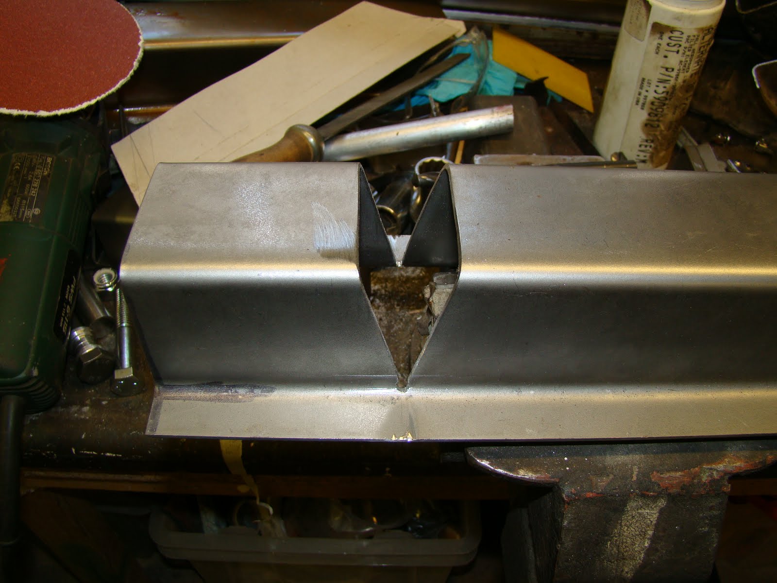
This will be my fourth attempt at welding these supports so I should be able to get it right by now. I folded up the piece needed to provide the space for the clearance of the shock when it swings forward and backwards.I used the bench to make sure the two pieces were straight with each other. So as I welded the two parts together I set the bench alight, and didn't notice until I couldn't see the weld through the smoke and had to lift up my welding mask.

With the clearance piece welded in and a few more trial fits I then reamed the shock mount holes with an adjustable reamer and used one of the bushes as a guide. This didn't really work as well as I hoped. The reamer wobbled because it was such a large diameter for using by hand and this caused it to cut a jagged hole. I should have put it in a pillar drill. The hole still came out with a snug fit for the bushes just not as clean as I had hoped.

A few more trial fits and I was able to mark where the swing arm wanted to foul the edge of the support. The clearance issue was sorted using a huge mallet, steel dolly and some old decking that used to cover up the fish pond. Yup, just like Thor.

This time I tried to bend the radius where the two parts met before it was welded in place. but I ended up bending the two edges at different heights and still needed to place a couple of cuts to relieve the bends. I later dressed (hit with a large mallet) the ends so they aligned once the support was welded in place

A picture before assemble because I got a bit snap happy with the camera.

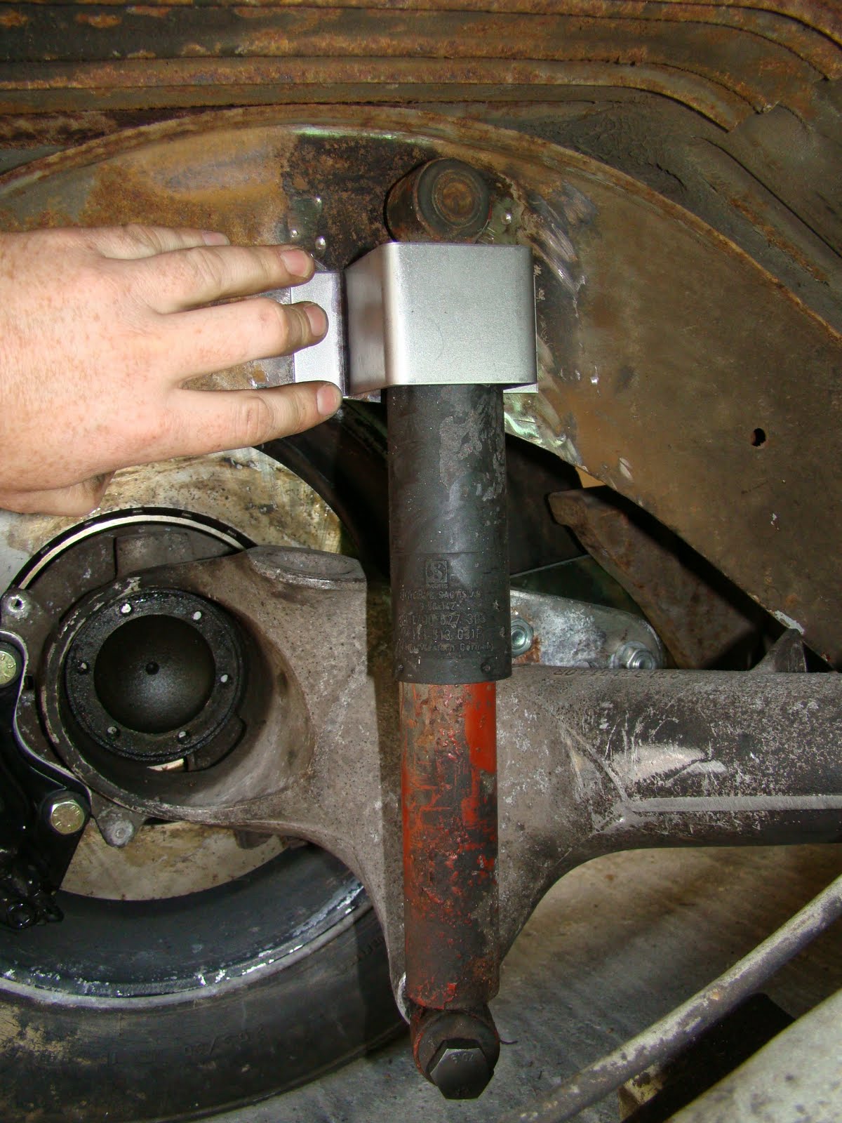
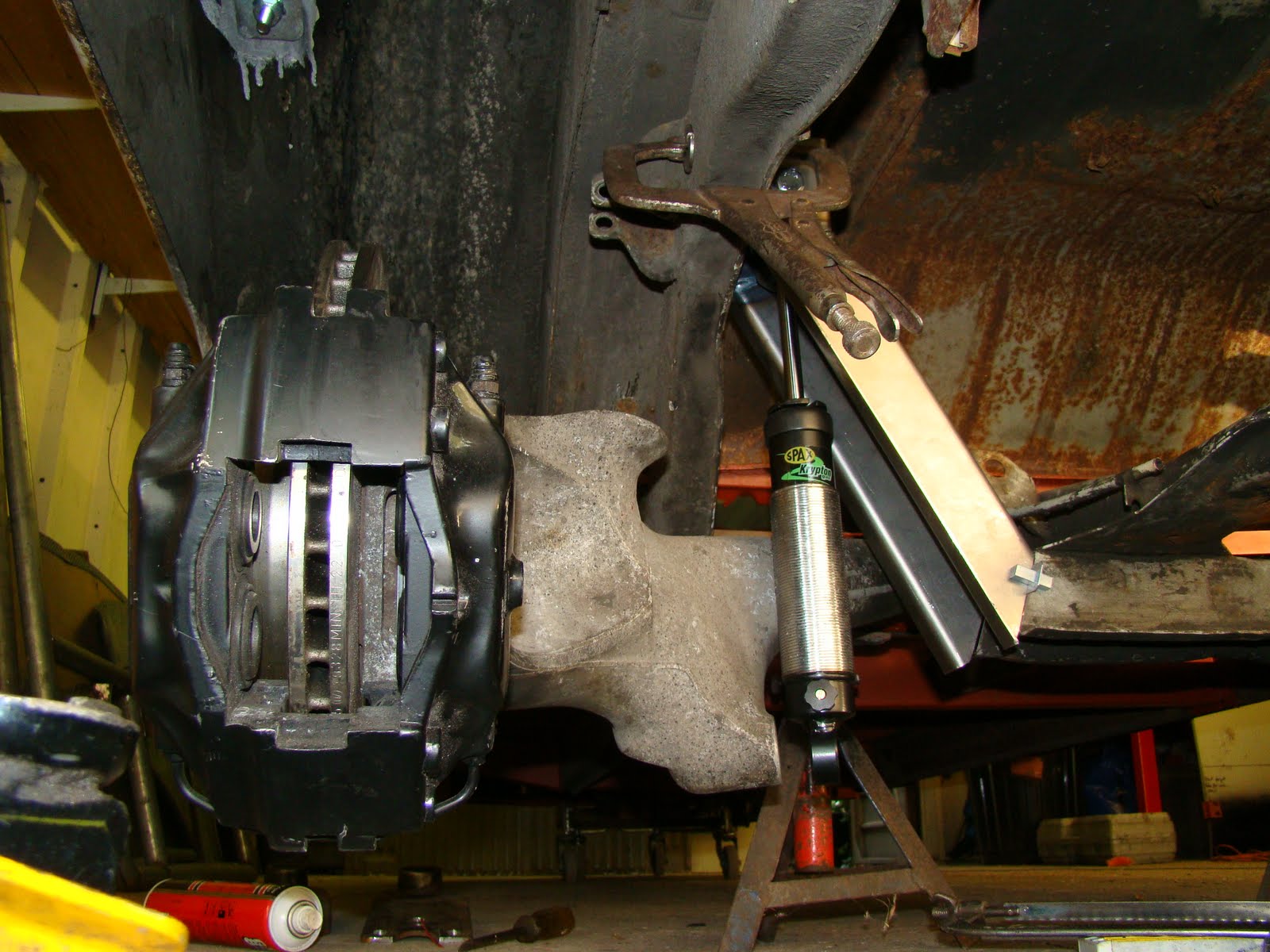
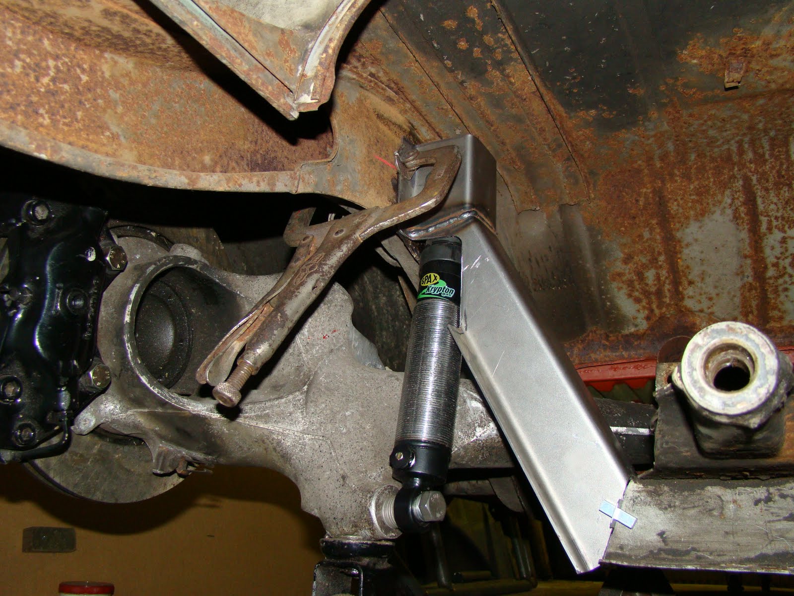
This is the support painted, assembled and checked for the shock clearance at the correct height for the top shock mount hole and the supports squareness with the other side.

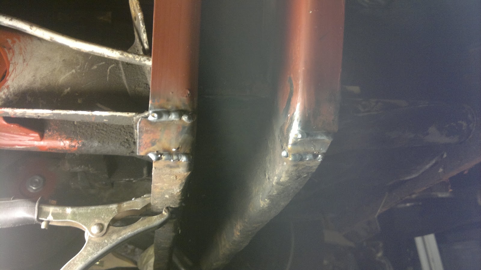
The A arm and shock was then removed and the support welded into place with a seam weld either side at the top and a seam weld inside and out at the bottom but finished flush to try and make it look like I'm good at welding. I may add another weld inside at the top as the skin it's welded to is thinner on the inside of the chassis than the outer where the original mount was welded. I have seen a shock mount  welded on the inside rip away from the chassis, so I will have to consider this.

I had one last bush to trim to size, so I used my new toy which took 5 minutes..

I could try and sort out an anti roll bar but I'll recondition the hand brake shoes first, sort the hand brake cable out, work out what length drive shafts I'll need and see if the wheels are straight and square with each other first.

Heres the parts I've made or had made to get this lot to all fit together.
With a couple of used tyres slung on the wheels the van is finally on the ground with its new rear end. This has taken a lot of work, too much time, mental skills and help from a few friends but is now finished (nearly), so up yours to who ever told me it could not be done.

Rear Shock Mounting for 944 IRS conversion Pt4

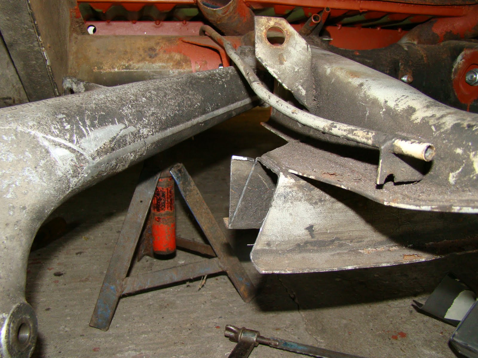
With the left shock mount welded in place I just needed to tidy up the excess material from the new section sticking out the bottom.
I sorted this out by cutting a bending block to the radius I wanted clamped it to the van then started hitting very hard with a really big hammer, this didn't quite work as I had hoped.
So I had to make a couple of strategic cuts with the angle grinder then start hitting it again really hard.
With the help of the gas torch I finally managed the bend I needed

Then welded up the gaps
Ground the welds down then hid the welding with some red oxide paint

With one side done I get to start on the other side.
With a little less disregard than the first time I cut the van up. I dug out the electric saw I had for cutting my hedge down, It took me 2 min to pull the support out.
Then cleaned up the surface of the spot welds so I could see where to drill them off.
With the old support out the way I can mark the cutting angles I need.
to be continued.......

Rear Shock Mount fitting for 944 IRS conversion Pt 3


I was able to visits my uncles workshop and turn down a couple of brass bushes to fit inside the top mount bearing this is because the bolts I'm using is 12mm and the bearing hole is 15mm. I also found out later I used the wrong cutting bit. that's a whole different world.
I also faced of one of the other bushes to give me the offset position I needed for the top mount. when at full extension the shock is vertical and the top mount collar just sits off the forward face, when compressed the shock swings back and because of the off set now sits clear of the back face.
Now that I'm happy with the top and bottom shock mounts I cat fit the new section. I removed the spring plate and A arm then clamped the lower part of the section with panel clamps and adjusted the top till it sat square with a bit of persuasion and also lined up with my previous marking of the highest and lowest position for the mount bolt.


With the upside down, on my back, stuck under the van, not able to move welding done and the spring plate and A arm fitted you can now see the final result.


I'll tidy the lower point and form a radius and then there's just the other side to do, just hope it does not take me 6 month's.

Rear Shock mount Fitting for 944 IRS conversion Pt 2

After messing up the width of the last top hat section I attempted to bend up some more, this took another trip to the metal shop and several more attempts at fabrication, all this just to get the width 1 mm thinner

With the old cardboard template from my first attempt I dug out from the pile of scrap metal, I marked out the angles needed for the bend with a small hole drilled in the corner to relieve the bend. A couple of blocks, a large clamp, 2 litres of coke and Thors' Hammer allowed me to make the bend.


A trial fit just once, twice or seven times allowed me to adjust the angles of the cuts slightly so it would fit. This meant climbing in and out of my engine bay on my hands and knees each time. I like my van to know it's the Boss in our relationship.


A couple of tack welds on the bend line while the section was clamped to the chassis rail and then it was removed to be seam welded and then attacked with the grinder to hide the bodgy welding.


I cut up some of the other section I'd made so that I could see if it was worth fitting these U sections inside the top mount area to strengthen the support but it would have been to awkward to spot or mig weld these in place and they would have reduced the clearance inside the top shock mount even more that it already is.


I also bought some brass oiled bushes, one top hat, two for clamping either side of the shock mount bearing and a third that can turn down to the required length to get the correct position for the top mount. The shock mount hole is 1/2" (12.7mm) or 15mm (with the supplied spacer removed) and the brass bushes could not be supplied in either internal size, so I went for 12mm internal with 18mm outer. This is the diametre of the regular shock mount bolts for a van.


With the position of the top mount holes calculated from the nominal extension and retraction of the shock taking into account the full range of the A arm and the compression of the bump stop. I then ignored that and drilled a couple of holes where I thought looked good. Fitted a 1/2" bolt from a Creative Engineering mount kit,  some bushes from a Demon Tweeks mount kit and a few washers allowed me to adjust the position of the mount forward and back to get the best position for inside clearance and shocks angle. 


This also meant cutting the chunk out of the section so the shock would tilt back as the wheel moved up. A few ideas were passed around by my design team as to how to overcome this weak spot and the best idea that I/we could come up with was to cover the shock keeping the existing angles. So I raided the cornflake packet again to work out what shape I'd need.


I also needed to clear the back of the section where the A arm moved up and rubbed. I cleared this originally by cutting it out with the grinder, This time I heated the section up and grabbed Thor's Hammer again to beat the whatever out of it. The blocks helped keep inline what needed to stay straight and I got to let all my aggression out. 


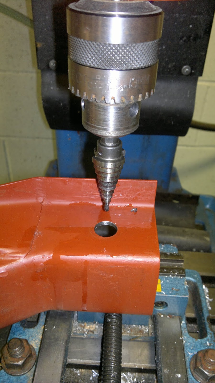
With most of the fabrication now sorted I can concentrate on getting the holes drilled for the top mount bushes. The price of a 18mm hss drill bit was £14.95 and too much for just 4 holes so I reluctantly borrowed a Christmas Tree hole cutter and attempted to drill a pair of parallel holes in an unsupported springy piece of folded steel, the use of the pillar drill did help.


To get the second hole drilled in the correct position I fitted the bush into the first 18mm hole then clamped it in the pillar drill vice, by slotting a 12mm drill into the bush and poking it out the other side I  was able to line up the tip of the hole cutter with the tip of the 12mm drill bit. I drilled away and it still looked a bit off. 


I just need to turn down the bushes to the correct length and I can then weld this side to the van and then do it all again for the other side. Whoop whoop.


Rear Shock Mount Fitting for 944 IRS conversion

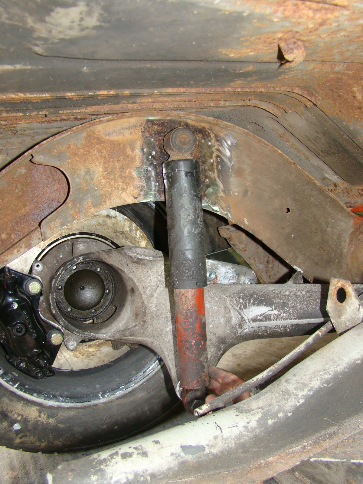
To fit a shock/damper from the 924 A arm to the chassis of the van is probably the biggest problem I've had with converting the rear suspension to IRS. One of the problems is that the curve of the gear box mount kind of gets in the way. Thinking I could buy a shock mount and weld it inside the chassis rails is not that easy.


So I decided to get the gearbox support out the way, I didn't take this decision lightly it took months of staring at my rear end thinking how to mount the rear shock. I plucked up the courage and went for it, drilling off the spot welds and cutting away the lower portion.


Once the curve was out the way I had the room to play about with different designs to see what would work. Here's a cereal packet cut and taped to make a wider top hat section that the original one to allow the shock to fit inside.

With the top hat cut out I took the measurements I needed and bent up two more sections to replace the one I'd cut away.


I had a lot of trouble try to get hold of the lower shock mount bolt that fits the 924 rear swing arm which is M14 x 1.5 x 85 (part no 900 082 054 02)  as Porsche no longer make them. After a long search on several forums I ended finding out about a stronger spec bolt from BMW the same size as the one I needed.
With a cutoff of new folded section I trialed the best place for the mount to fit. I now found that the lower bolt was at a slight toe in angle and tilted the top of the shock  into the centre of the van, This meant there was not enough play in the rubber mounts to take up the now angled position of the shock. I tried to sort this by buying some Creative Engineering shock mounts, these would allow me to turn the top shock hole 90 deg. But to fit these I would have had to drill through the chassis and it would have been easier to just weld a tube between the two skins of the chassis.

Taking the angle from the cereal packet template from earlier I cut and bent the top hat section for a trial fit over the shock.
Again after another mammoth search I was able to get a pair of custom shocks from SPAX made with ball joints at either end to alleviate the problem of the lower shock bolt being at an awkward angle. To spec the shocks using Spax online chart I worked out the extension and compression to give me the total movement, then worked out what ends I'd need, then added a built in bump stop. 
Spax also helped me by providing a couple of aluminium spacers to pack out the gap between the 14mm lower bolt and the 15mm bearing, these would usually come with a 12mm spacer that I had it push out to fit the spacers. I cut the larger bump stop off the shaft and worked out I needed a 10-14mm spacer to pack out the lower mount.
Again using my cardboard template I marked then cut the angles in the top hat section and drilled a hole at the tip of the cuts for stress relief in the bend.
I then cut the original section to the angle I needed. I should have left a lot more material on this part so that the angle of the top mating pieces were equal as this would have made a neater joint.

This is the section trial fitted, I'm hopping to spot weld the top section to the chassis. You can see where the lip of the lower portion don't come together because of the uneven angle where the two meet

 I'm not sure how but the profile of the new section didn't match up with the old one. I thought I had this spot on. With a bit of thought on how I can make this fit, welding it together with a lap joint or just beating the hell out of it. I decided it would be better to fold up a new piece.
Instead of putting that to one side due to my cock up, I decided to use this as a trial piece for the shock mounting position. I grabbed a few large washers and spacers from a shock mount I brought from Demon Tweaks that didn't fit. I then welded up the seam at the bend and fitted the shock in the top hat section with a 1/2 inch bolt that went all the way through.
With the shock at full extension and the A arm at full drop the shock was a little lower that the bottom mount point which meant my calculation for the extension worked out OK. 
Plenty of clearance inside the box section for the top of the mount.

Then compressing the shock It all went Pete Tong (English rhyming slang my American friends). The body of the shock fouled on the back edge of the section, because as it moves up the lower mount also moves slightly back. After half an hour of huffing and fiddling I decided to cut away the fouling section to see where it should sit naturally. Getting a call from the house for Sunday dinner I've had to leave the problem there for now, and have passed the details on to my design consultants. Hope they come up with something, as I haven't got a clue what to do. Maybe I shouldn't have cut the original support out!